THE PURPOSE of this primer is to introduce the technology used in CMOS image sensors as well as promoting a better understanding of the consumer product potential unleashed as the Internet, digital imaging and integrated information appliances converge. It is assumed that the reader is familiar with some basic physics and semiconductor technology, but most of this overview covers entry level imaging technology information.
THIS DOCUMENT starts with the basics of light and builds on this information to bring an understanding of CMOS imagers. Also included are some terms and phrases you may run into in the digital imaging industry.
Light
Photons
Color
The Human Eye
Color Mixing and ReproductionBinary Representation of Pictures
Standard Spatial Resolutions
Digital Representation of Pixels
Visible light is the band of electromagnetic radiation that can be sensed by the human eye. Electromagnetic radiation is the type of energy, traveling in a wave that is produced by an oscillating charge or energy source. Electromagnetic ("EM") waves also include radio waves, x-rays and gamma rays.
An electromagnetic wave can be defined by its wavelength (measure of length peak-to-peak) or its frequency (number of cycles per second). The multiplication of these two characteristics is a constant - the speed of light - so the two are inversely proportional to one another. That is, the shorter the wavelength, the faster the frequency, the longer the wavelength, the slower the frequency.
Visible light is usually referred to in wavelength (instead of frequency) and includes wavelengths of 400 nanometers (10 -9 meters, abbreviated "nm") to 750 nm. Ultraviolet and infrared refer to the wavelengths just beyond the ends of the visible electromagnetic spectrum:
| Wavelength Band | Type of Radiation | Frequency (cycles per second) |
| ~10 -14 meters | Gamma Rays | ~10 22 |
| ~10 -9 meters (nanometer) | X Rays | ~10 17 |
| ~10 -7 meters | Ultraviolet | ~10 15 |
| ~10 -6 meters | Visible Light | ~10 14 |
| ~10 -5 meters | Infrared | ~10 13 |
| ~10 -2 meter (centimeter) | Short Wave Radio | ~10 10 |
| ~1 meter | TV and FM Radio | ~10 8 |
| ~10 2 meters | AM Radio | ~10 6 (megahertz) |
| ~10 6 meters | Long Wave Radios | ~10 2 |
Measurements approximate. The product of the wavelength times the frequency equals 3x10⁸ meters per second, the speed of light.
Everyday usage of this chart is heard in the terms "short wave radio" and "900MHz cordless phone".
While light has properties of waves, the energy carried by light is not distributed in a wave, but carried in discrete bundles (or "quantized"), giving light some properties like particles. These light "particles" are called photons, and are referred to when explaining how light transfers energy and are used to explain how CMOS Imagers transfer light energy to electrical energy.
The Visible Light band in the EM spectrum can be broken down into a series of colors, each color corresponding to a different wavelength. The typical spectrum that is displayed is seven colors - red, orange, yellow, green, blue, indigo, and violet. In reality the band represents a continuum of colors, each corresponding to a different wavelength, but seven colors are historically displayed. The bands outside this region - ultraviolet and infrared - are said to be beyond the range of the human eye, although in experiments both ultraviolet and infrared light can be seen unaided in certain conditions.

| 400nm |
500nm
|
600nm
|
The human eye can discriminate between hundreds of wavelengths as well as the intensity of the light source being received. The ability to distinguish these characteristics is through two main types of sensory cells in the retina:
rods - Rods convert photons into an electrical impulse that is processed by the brain. Rod cells are stimulated by the intensity of light and are responsible for perceiving the size, shape, and brightness of visual images. They do not perceive color and fine detail; tasks performed by the other major type of light-sensitive cell, the cone. The rods are what are in use when you are in the dark, meaning a red stop sign looks gray when you look at one without the aid of your car's headlights.
cones - Cones are less sensitive to low illumination levels, but give us our color vision. There are three types of cones, each of which contains a distinctive type of pigment. One cone absorbs red light, another green, and the third type blue. A given color stimulates all three types of receptors with varying effectiveness; the pattern of these responses determines the color perceived. This color breakdown is explained more in color reproduction, below.
The mnemonic to remember which cells does what is that Cones receive Color and both start with a "C"! Rod cells are not only much more sensitive to light than cones but are also much more numerous. The human eye contains about 130 million rods to about 7 million cones. This means that the human eye is much more sensitive to the intensity of the light than its color. This characteristic is taken advantage of in color processing, which will be covered later.
This basic problem of color reproduction comes down to the question of how to create all the colors that are possible in the color spectrum. Over the years, it has been discovered that all the colors in the spectrum can be recreated from only a sub sample of only three other colors by mixing them in varying degrees.
The fact that the whole range of colors may be synthesized from only three primary colors is essentially a description of the process by which the eye processes colors. This is a fortunate property of vision since it allows three colors to represent any of the 10,000 or more colors (and brightness) that may be distinguished by human vision. If this was not the case and vision was dependent on the energy and wavelength relationship of light described above, it is doubtful that color reproduction could be incorporated in any mass-communication system.
The three main ways to reproduce color are as follows:
YCRCB - Luminance, Chrominance (Red), Chrominance (Blue) - The third way to characterize light makes use of the RGB concept above, but breaks down the color components in different fashion. Any color can be broken down into two qualities:
Luminance - Its brightness or intensity. Remember that the human eye that is more sensitive to brightness than to color. The luminance value, stated with the letter "Y", is the brightness breakdown of the color.
Chrominance - the color "remaining" once luminance is removed. This can be broken down again into two independent qualities:
Hue - This is the color of the light, in this case red or blue.
Saturation - the relative purity, or the amount of white light mixed with a hue. High saturation colors contain little or no white light.
The translation from RGB to YCRCB is done with a "look-up table" which takes any RGB value and matches it to its corresponding YCRCB components.
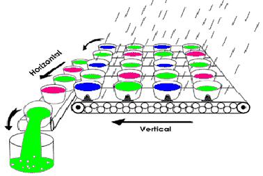
The fact that color can be broken down into individual components is extremely important to digital imaging - the process of breaking down a picture into the "1"s and "0" of digital communications. The process of breaking down a picture into individual components can be done in two basic steps:
Breaking down the picture into a pixel grid - For a picture to be described as a series of 1s and 0s, it first must be broken down into a grid, or array. This process simply places a grid over a picture and assigns a single color for each square in the grid. This single color grid square is called a "pixel" (short for picture element).
The number of pixels used for the picture breakdown is called the "spatial resolution" and is usually referred to by its horizontal and vertical number of pixels, such as "640x480", meaning 640 pixels horizontally and 480 pixels vertically.
For a given picture, the number of pixels will determine the quality of the digital picture. That is, the smaller number of pixels, the larger they must be and the lower the picture quality. The higher number of pixels, the smaller each pixel is and the better the picture quality:
|
Low Spatial Resolution
|
High Spatial Resolution
|
|||
 |
 |
|||
| Large Pixel Size Fewer Pixels Low Picture Quality |
Small Pixel Size More Pixels High Picture Quality |
There are a number of standard resolutions, or arrays, in the sensor industry. Most of these formats come from the display monitor industry, which drives the number of pixels you see on computer monitors. Since sensors typically display on monitors, they commonly match monitor resolutions. Term one will hear in regards to spatial format include:
CIF - Common Intermediate Format - 352 x 288 pixels for a total of 101,376 pixels (commonly referred rounded at 100,000 pixels). This format was developed for PC video conferencing. The number of pixels is fairly small, but was needed in order to get full motion video at 30 frames per second.
QCIF - Quarter CIF - One quarter of a CIF format, so 176x144 for a total of about 25,000.
VGA - Video Graphics Array - 640x480 pixels for a total of 307,200 pixels. The VGA format was developed for computer monitors by IBM and become the standard for monitors for many years. Although monitor resolutions today are higher, VGA is still lowest "common" display which all PCs will support.
SVGA - Super VGA - 800x600 pixels for a total of 480,000 pixels. The next highest monitor resolution developed for PCs.
XGA - "Xtended" Graphics Array - 1024x768 for a total of 786,432 pixels. Another monitor standard.
If a sensor is not one of these standards, its resolution is simply displayed as vertical by horizontal (200x300, for example). Typically, if a sensor has more than 1 million total pixels (anything more than 1000x1000 pixels), it is termed a "megapixel" sensor, which has come to mean any sensor with more than one million pixels.
Now that the picture is represented as an array of pixels, each pixel needs to be described digitally. To do this, each pixel is assigned two main components: its location in the picture and its color. Its location is usually just represented by its "x and y" coordinate in the grid. Its color is represented by its color resolution, which is the method of describing a color digitally.
Using the RGB method of color representation, a color can be divided into an arbitrary number of levels of that color. For example, red can be broken down from total red to no red (or white):
|
|
|
| No Red |
Total Red
|
Each step in the arbitrary breakdown is called a "gray level" (even though the color is not gray). The same breakdown can be done for green and blue.
By experiment, the naked eye can distinguish about 250 shades of each color. Using binary math, the closest binary number is 256, which is 28, gray levels can be used for each color. This means for each color component of a picture, there are 8-bits used for each R, G, B element, for a total of 24 bits of color representation. The complete R, G, breakdown of 224 colors represents about 16.7 million colors that can be represented digitally. The number of colors represented by a pixel is called its "tonal resolution" or its "color dynamic range". If fewer bits are used, the number of colors represented is smaller, so its dynamic range is smaller.
Image sensors are devices that take an image and directly convert it to a digital image. Referred to in marketing literature as "silicon firm" or "silicon eyes", these devices are made of silicon since silicon has the properties of both being sensitive to light in the visible spectrum and being able to have circuitry integrated on-board. Silicon image sensors come in two broad classes:
Charge-Coupled Devices (CCD) - Currently the most commonly used image sensor, CCDs capture light onto an array of light-sensitive diodes, each diode representing one pixel. For color imagers, each pixel is coated with a film of red, green, or blue (or complementary color scheme) so that each particular pixel captures that one particular color.
The pixel, made up of a light sensitive diode, converts the light photon into a charge, and the value of that charge is moved to a single location in a manner similar to a row of people passing buckets of water. At the end, the charge is amplified. Since this "bucket brigade" is accomplished by applying different voltages to the pixels in a succession, the process is called charge-coupling. Because the value in the pixel is moved by applying different voltages, CCD sensors must be supported by several external voltage generators. In addition, CCDs require a specialized manufacturing process that cannot be used by any other device.
| Graphical representation of CCD |
Image source: Digital Photography Review
|
CMOS Imagers - Like CCDs, these imagers are made from silicon, but as the name implies, the process they are made in is called CMOS, which stands for Complementary Metal Oxide Semiconductor. This process is today the most common method of making processors and memories, meaning CMOS Imagers take advantage of the process and cost advancements created by these other high-volume devices.
Like CCDs, CMOS imagers include an array of photo-sensitive diodes, one diode within each pixel. Unlike CCDs, however, each pixel in a CMOS imager has its own individual amplifier integrated inside. Since each pixel has its own amplifier, the pixel is referred to as an "active pixel". (note: There are also "passive pixel sensors" (pps) that do not contain this amplifier). In addition, each pixel in a CMOS imager can be read directly on an x-y coordinate system, rather than through the "bucket-brigade" process of a CCD. This means that while a CCD pixel always transfers a charge, a CMOS pixel always detects a photon directly, converts it to a voltage and transfers the information directly to the output. This fundamental difference in how information is read out of the imager, coupled with the manufacturing process, gives CMOS Imagers several advantages over CCDs.
CMOS Sensor Array
Due to both design and manufacturing considerations, there are a number of advantages that CMOS Imagers have over CCD:
Integration - Because CMOS Imagers are created in the same process as
processors, memories and other major components, CMOS Imagers can
integrated with these same components onto a single piece of silicon. In
contrast, CCDs are made in a specialized process and require multiple
clocks and inputs. This feature limits CCDs to discrete systems, which in
the long run will put CMOS Imagers at a cost advantage, as well as limit
what kinds of portable devices CCDs can be integrated into.
Reduced Power Consumption - because of all the external clocks needed
to "bucket brigade" each pixel, CCDs are inherently power
hungry. Every clock is essentially charging and discharging large
capacitors in the CCD array. In contrast CMOS imagers require only a
single voltage input and clock, meaning they consume much less power than
CCDs, a feature that is critical for portable, battery operated devices.
Pixel Addressibility - CCDs use of the bucket brigade to transfer pixel
values means that individual pixels in a CCD cannot be read individually.
CMOS imagers on the other hand have the pixels in an x-y grid allowing
pixels to be read individually. This means that CMOS imagers will be able
to do functions such as "windowing", where only a small sample
of the imager is read, image stabilization to remove jitters from
camcorders, motion tracking and other advanced imaging techniques
internally that CCDs cannot do.
Manufacturing Cost - Since CMOS imagers are manufactured in the same
process as memories, processors and other high-volume devices, CMOS
imagers can take advantage of process improvements and cost reductions
these devices drive throughout the industry.
There are a number of phrases and terms for describing the functional capability, physical features or competitive characteristics of an imager:
Active Pixel Sensor (also APS) - As explained above, an active CMOS Imager pixel has its own amplifier for boosting the pixel's signal. Active Pixels are the dominant type of CMOS Imagers in the commercial market today. The other type of CMOS Imager, a passive pixel sensor (PPS), consists of only the photo detector without a local amplifier. While very sensitive to low light conditions, these types of sensors are not suitable for commercial applications due to their high amount of noise and poor picture quality when compared to active pixels.
Fill Factor - The amount of a CMOS Pixel that is actually capturing light. In an active pixel, both the photo detector and the amplifier take up "real estate" in the pixel. The amplifier is not sensitive to light, so this part of the pixel area is lost when taking a picture.
The fill factor is simply the percentage of the area of the pixel that is
sensitive to light. In the picture above, this is about 40%. As semiconductor
process technologies get smaller and smaller, the amount of area taken up by the
amplifier is taking up less space, so low fill factors are becoming less of an
issue with active pixels. Note that in passive pixels - where there is no
amplifier at all - fill factors typically reach over 80%. The reason they do not
reach 100% is due to routing and pixel selection circuitry that are also needed
in a CMOS imager.
Microlenses - In some pixel designs, the fill factor becomes too small
to be effective. For example, if a fill factor in an imager were 25%, this would
mean that 75% of the light falling on a pixel would be lost, reducing the
pixel's capability. To get around this situation, some CMOS imagers have small
lenses manufactured directly above the pixel to focus the light towards the
active portion that would otherwise fall on the non-light sensitive portion of
the pixel. Microlenses typically can increase the effective fill factor by two
to three times.
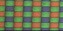
Color Filter Array (also CFA or just "color filter") - CMOS
Pixels are sensitive to light photons but are not, by themselves, sensitive to
color. Unaided, the pixels will capture any kind of light, creating a black and
white image. In order to distinguish between colors, filters are put on top of a
pixel to allow only certain colors to pass, turning the "rods" of the
array into "cones". Since all colors can be broken down into an RGB or
CMYk pattern, individual primary or complementary color schemes are deposited on
top of the pixel array. After being read from the sensor, software takes the
different values of the pattern and recombines the colors to match the original
picture. There are a variety of different filters, the most popular being the Bayer
Filter Pattern (also known as RGBG). Note the large amount of green in the
pattern, due to the fact that the eye is most sensitive to color in the green
part of the spectrum.
|
|
Bayer Color Filter Pattern
|
Read Noise (also called temporal noise) - This type of noise
occurs randomly and is generated by the basic noise characteristics of
electronic components. This type of noise looks like the "snow" on
a bad TV reception.
Fixed Pattern Noise (also FPN) - This noise is a result of each
pixel in an imager having its own amplifier. Even though the design of each
amplifier is the same, when manufactured, these amplifiers may have slightly
different offset and gain characteristics. This means for any picture given,
if certain pixels are boosting the signal for every picture taken, they will
create the same pattern again and again, hence the name.
Blooming - The situation where too many photons are being produced to be received by a pixel. The pixel overflows and causes the photons to go to adjacent pixels. Blooming is similar to overexposure in film photography, except that in digital imaging, the result is a number of vertical and/or horizontal streaks appearing from the light source in the picture.
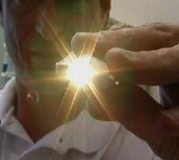 |
This photo illustrates two undesirable characteristics: blooming, the slight vertical line running from the top to the bottom of the picture and lens flare, the star shape light which is a function of the lens and not the imager. |
Optical Format - is a number in inches that is calculated by taking the diagonal measurement of a sensor array in millimeters and dividing by 16. For example, a CMOS Imager that has a diagonal measurement of 4mm has an optical format of 4/16, or ¼".
What Optical Format calculates is the type of lens system that must be used with the imager. In the lens industry, there are standard sets of ¼", ½", ¾", etc. lens systems. By using Optical Format, a user of imagers can use standard, mass-produced (and inexpensive) lens systems rather than having to design and custom build a special lens system. The terms and measurement comes from the days of electron tubes and pre-dates solid-state electronics. Generally speaking, larger optics are more expensive, so a ¼" lens system is less than a 1/3" lens system.
Aspect Ratio - The ratio between the height and width of a sensor or display. It is found by dividing the vertical number of pixels (height) by the horizontal number of pixels (width) leaving it in fractional format.
For example, a pixel with resolution of 640x480 would have an aspect ration of 480/640= ¾.
The most common aspect ratios are ¾ and 9/16. The ¾ aspect ratio is the ratio for computer monitors and TVs. The newer 9/16 aspect ratio is used for High Definition Television (HDTV)
Quantum Efficiency (or QE) - Imagers create digital images by converting photon energy to electrical energy. The efficiency in which each photon is converted to an electron is the imager's quantum efficiency. The number is calculated by simply dividing electrons by photons, or E/P. If no electrons are created, the efficiency is obviously zero, while if each photon creates one electron the efficiency is 100%. Typically, a sensor has different efficiency at different light frequencies, so a graph of the quantum efficiency over the different wavelengths is typically shown:
Dark Current - A situation in CMOS imagers where the pixels fill with thermally created electrons without any illumination. This problem is a function of the manufacturing process and layout and increases with increasing temperature.