|
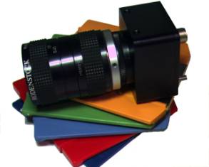
SI-3300RGB MegaCamera™ 3.2 Megapixel, 10-Bit, 40/80MHz Progressive Scan Digital Camera |
Silicon
Imaging Inc.  |
|
Silicon Imaging is proud to continue its innovation in high-resolution color vision camera. Driven by the growing demand for consumer Digital Still Cameras, CMOS sensors are continuing to break technical barriers and surpass the performance characteristics of CCD’s in many photonic, imaging and consumer applications. By utilizing a single highly integrated CMOS device, which incorporates Megapixel sensing areas, timing generation, signal processing and high bandwidth outputs, Silicon Imaging has developed a very compact, low-power, ultra high speed Megapixel digital camera system. 2048
x 1536 Megapixel (3.2MP) - Ultra Resolution 10-Bits
Sampling – Sub-Pixel Accuracy Subsampling
with Binning – Video Preview 1000FPS
Windowing and 720/1080P HD Modes Automatic
Black Level Correction CameraLink
Digital Interface - 57.6K Serial Mode
GigE-Cameralink – Gigabit Ethernet Connectivity Now you can capture high-speed MegaCamera images to your PC from distance of a 100-meters using CAT-5 wire using the Silicon Imaging GigE-CameraLink Interface. The GigE-Cameralink captures MegaCamera digital images and transmits them via 10/100/1000 Gigabit Ethernet directly to your PC at speeds over 100MB/sec.
|
|
SI-3300 MegaCamera CameraLink Specifications
SI-3300
Sensor:
|
Active
Pixels |
2.048H
x 1,536V |
|
Optical
Format |
1/2”
(6.83mm
x 5.45mm) |
|
Pixel
Size (pitch) |
3.2
µm x 3.2 µm |
|
Pixel
Type |
CMOS
|
|
Aspect
Ratio |
1
: 1 |
|
Spectral
Response |
350
~ 1000 nm |
|
Peak
QE |
56%
Monochrome @ 570nm |
|
Minimum
Illumination: |
0.3
lux nominal (SNR =1,
f# = 2.8, exposure = 100ms, daylight) |
|
Responsivity |
2.1
V/lux-sec |
|
Dark
Current @ 25°C |
20
e-/sec |
|
Temporal
Noise |
10
e- |
|
Saturation
Charge |
40,000
e- |
| SNR | >43dB (MAX) |
|
Dynamic
range |
61
dB |
|
Windowing
(ROI) |
Horizontal
& Vertical speed increase |
|
Sub-sampling |
Full,
1/2, 1/4, 1/8 |
|
Gain
MAX |
15X,
min step size 0.125 |
|
Readout
Method |
Progressive
Scan |
|
Black
Level |
Auto
Black Level Calibration |
|
Shutter |
Rolling
Shutter and Single Frame |
|
Shutter Speed |
Variable,
1 to 16383
row times |
|
Horizontal
Blanking |
244
Clocks/line |
|
Minimum
Row Time |
548
Clocks (304+ 244
Blanking) |
|
Vertical
Blanking |
25
Rows |
A/D
Conversion & Sampling Clock Synthesizer
|
A/D
Conversion |
Nominal 48Mhz (12fps @ 3.1MP) |
|
Vertical
Resolution |
10
Bit (Format = 12bit-CL
1-Tap) |
|
Pixel
Clock Frequency |
20
~ 60 Mhz Programmable 20
~ 80 Mhz (-H High-Speed) |
|
Adjustment
Method |
Serial
command Protocol |
|
Mean
Black Level |
32
Counts |
Digital
Video Output
|
Readout
Rate |
20
~ 85Mhz x 12bit format |
|
|
Readout
Format |
CL-12 (Duplicated on Ports A, B) |
|
|
Frame
Rate 1280
x 1024 1280
x 720 640
x 480 320
x 240 200
x200 160
x 120 |
48MHz 30 43 110 334 407 654 |
60MHz 38 54 137 417 509 817 |
| Frame Time (default) | 1524 x 1050 rows @48MHz = 30fps | |
CameraLink
Frame Grabber Control:
|
Serial
Communication |
RS-232
Protocol 9600bps (57.6k) |
|
Signaling |
TX
& RX (LVDS) |
|
Asynchronous
Triggers |
LVDS
– CC1 (-CL) |
|
Region-of–Interest |
Programmable
Horiz & Vertical |
|
Programmable
Modes |
Exposure,
Gain, Windowing, Clock rates, Auto black, image mirroring. |
|
Gains |
Individual
RGB Gains Range:
15X, MIN step size 0.125 |
|
Setting
Timing |
Next
top of Frame |
|
Ext
Clock Sync |
Clock
in or Clock Out (-X Option) |
Power
|
Input
Voltage |
+5
VDC +/- 10% |
|
Power |
2.5
Watts |
|
Power/Trigger
Connection |
Tajimi
RO3-PB3M 3Pin (-CL) |
Mechanical
|
Lens
Mount |
C-Mount,
7mm Back focus Adj. |
|
Enclosure
Size |
45mm
W x 52mm H x 50mm L |
|
Weight |
12
oz. |
|
Camera
Mount |
¼”
x 20 standard tripod mount |
|
Cable
Connector |
Cameralink
MDR-26 |
Spectral
Response Curve (RGB Model Only)
|
Command |
Clock
Rate MHz |
SI-3300 Frame Rate |
||||||
|
|
MHz |
2048
x 1536 |
1600
x1200 |
1920x1080 |
1280x720 |
640
x480 |
320
x240 |
128
x128 |
|
lc306886 |
20 |
5 |
8 |
8 |
17 |
40 |
122 |
148 |
|
lc30b689 |
25 |
7 |
10 |
10 |
21 |
50 |
152 |
185 |
|
lc37cb8f |
30 |
8 |
13 |
12 |
25 |
60 |
182 |
222 |
|
lc35d40b |
35 |
9 |
15 |
14 |
29 |
70 |
213 |
259 |
|
lc306882 |
40 |
11 |
17 |
16 |
33 |
80 |
243 |
296 |
|
lc35e709 |
45 |
12 |
19 |
18 |
37 |
90 |
274 |
333 |
|
lc36a20f |
48 |
13 |
20 |
19 |
40 |
96 |
292 |
355 |
|
lc34b689 |
50 |
13 |
21 |
20 |
41 |
100 |
304 |
370 |
|
lc34b688 |
55 |
15 |
23 |
22 |
45 |
110 |
334 |
407 |
|
lc36cb8f |
60 |
16 |
25 |
24 |
50 |
120 |
365 |
444 |
|
lc367307 |
65 |
17 |
27 |
26 |
54 |
130 |
395 |
481 |
|
lc36ee0f |
70 |
19 |
29 |
28 |
58 |
140 |
426 |
518 |
|
lc36f88f |
73 |
19 |
30 |
29 |
60 |
147 |
446 |
542 |
|
lc34ae05 |
75 |
20 |
31 |
30 |
62 |
150 |
456 |
555 |
SI-3300 Register Programming
|
0x00 |
Chip
Version |
0x8421
0x8431 |
|
|
0x01 |
Row
Start |
0x000C
(12) |
(First row to be read out
+ 12) |
|
0x02 |
Column
Start |
0x0014 (20) |
(First
column to be read out + 14) Register
value must be an even number. |
|
0x03 |
Window
Height |
0x03FF (1023) |
Window
height (number of rows - 1) Min =
0x0002. |
|
0x04 |
Window
Width |
0x04FF (1279) |
Window
width (number of columns - 1) Register
value must be an odd number. Min = 0x0003 |
|
0x05 |
Horizontal
Blanking |
0x0013 (19) |
Number of extra row blanking clocks + 19 Row Blanking = 244 clocks + (Regx05 –19) |
|
0x06 |
Vertical
Blanking |
0x0019
(25) |
Number of extra rows added into the vertical blanking
period. Typically used
to slow down frame rate and allow time for register updates between
images. |
|
0x09 |
Exposure |
0x0419
(1049) |
Number of rows of integration |
|
0x0C |
Shutter
Delay (Short
Exposure) |
0x0000 (0) |
Number
of master clocks times 4 that the sensor waits before asserting the
reset for a given row. |
|
0x1E |
Subsampling &
Snapshot Mode |
0x80xx (x8000) |
0
0 (do not
change) 1
0 (do not
change) 2
Column Skip 4—default
is 0 (disable), 1 = enable. 3
Row Skip 4—default
is 0 (disable), 1 = enable. 4
Column Skip 8—default
is 0 (disable), 1 = enable. 5
Row Skip 8—default
is 0 (disable), 1 = enable. 6
0 (do not
change). 7
0 (do not
change). 8
Snapshot Mode—default
is 0 (continuous mode).1 = enable
Snaphsot
TRIGGER can come from CC-1 or from serial
interface
command. |
|
0x20 |
Subsampling
2 &
Scan Reversal |
0x11xx (0x1104) |
0
No bad frames:
0 (default) = only
good frames, 1 = all frames 1
0 (do not change) 2
1 (do not
change) 3
Column skip2:
0= normal
readout (default), 1=
skip by 2 4
Row skip2:
0 = normal readout (default),
1= skip by 2 5
0 (do not
change) 6
0 (do not
change) 7
Flip Row:
0 = normal,
1= Scan reversal 8
1 (do not
change) |
|
0x2B |
Green1
Gain |
0x0008
(8) 1x
gain. |
Gain Increments
Settings 1.000 to 4.000
0.125
0x08 to 0x20 4.25
to 8.00
0.25 0x51
to 0x60
9.0 to 15.0
1.0 0x61
to 0x67 |
|
0x2C |
Blue
Gain |
0x0008 (8) 1x gain. |
|
|
0x2D |
Red
Gain |
0x0008
(8) 1x gain. |
|
|
0x2E |
Green2
Gain |
0x0008
(8) 1x gain. |
|
|
0x35 |
Global
Gain |
0x0008 (8) 1x gain. |
This register can be used to set all four gains at once. When read, it will return the value stored in Reg0x2B. |
SI-3300
READOUT
MODES
There
are three operating modes for the SI-3300 cameras: Continuous, Frame
Snapshot and Genlock modes. Each
has its own characteristics shown below
|
“c” |
Continuous Electronic Rolling Shutter Operation. Return to ERS after an “f” or “g” |
|
“f” |
Arm
single frame capture. Trigger frame capture & readout if already armed.
In Frame snapshop there are 2 methods of Readout
|
|
“g” |
Enter Genlock Mode. Use “c” to return to continuous (supported by -H model) |
Continuous,
Electronic Rolling Shutter (ERS) – “c” Mode
Continuous,
rolling shutter mode is the default mode of operation of the camera. The
exposure is determined by the delay between two scans of the pixel array
and controlled with the shutter width registers, Reg0x08 and Reg0x09. The
shutter width is measured in row times. The first scan (shutter) resets
each row of pixels in turn, starting the exposure. The second scan (read)
stops the exposure by transferring the accumulated charge from each row of
pixels to sample/hold capacitors at the foot of the columns and reads the
(digitized) values out. When each scan reaches the bottom of the array
there follows a blanking period (controlled by the user) after which the
scan automatically restarts at the top of the array. Read out is therefore
continuous.
Frame
Snapshot Mode, with ERS – “f” Mode with ERS
The
snapshot mode allows capture of a single frame initiated by an external
trigger using CC-1, TTL-Trigger (-T option) or software command (‘f <cr>)’,
with the capability of controlling a flash using the Strobe_Out signal.
Each of the rows in the shutter will be reset, as shown in Figure.
Just as for continuous mode the exposure is determined by the delay
between the scans. However, before the start of the frame, the sensor
waits for a trigger before starting the scan. The first (shutter) scan
does not start until a rising edge on the TRIGGER signal is seen. The
second scan then follows after the shutter width delay. After the end of
the frame, the sensor waits for another trigger before restarting the
scan. The maximum snapshot rate is limited to half the continuous readout
rate. Note that the exposure
(shutter width) is still determined electronically.
To
return to Continuous ERS Readout mode, send a ‘c’ command.
Frame
Snapshot Mode with Global Reset - “f” mode (with Reg21 = x0003)
- T Model
|
0x21 |
Global
Reset or ERS Readout Mode |
0x0000
(ERS) or 0x0003
(GR) |
Set
to x0003 for Global Reset Snaphsot mode - Release all pixels from
reset simultaneously (use with flash & mechanical shutter.
x0000: for ERS. Default
Mode is conitunous ERS Note:
Global reset requires model SI3300–T with external trigger
cable. |
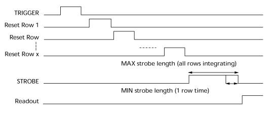
A
further enhancement to the snapshot capability is a global reset mode that
enables all pixels to start exposure to the scene simultaneously. Global
reset mode is selected by Reg0x21 to x0003 (x0000 is Rolling Shutter).
Global
reset mode has to operate with a mechanical shutter to terminate the
exposure time or with a strobe with minimum ambient light. Using the
global reset feature changes the behavior of the row reset controls.
Instead of pulsing, the resets are held on. As the shutter pointer moves
through the rows the resets are turned on one by one. When all of the rows
have been reset, the exposure is started by releasing them all together.
Exposure is terminated when an external mechanical shutter cuts off
the light. Row read out is performed after the exposure is terminated. The
strobe can be used to control flash and/or a mechanical shutter to end the
exposure of the array prior to readout.
To
enter Snaphshot mode with global Reset:
ly210003 <cr>
Global Reset Mode
f <cr>
Frame Snapshot Mode
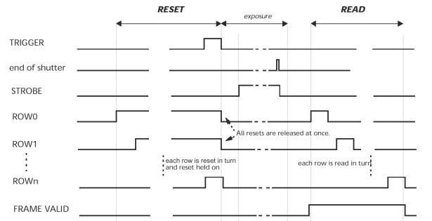
The
snapshot is initiated with the CC-1 Trigger, TTL-Trigger (-T option)
signal or “f’ frame request command, as in ERS snapshot mode. The
array is reset row by row before the sensor waits for the trigger. All of
the rows are held in reset until a rising edge is detected on the TRIGGER
input, whereupon they are all released at once. At this point every row in
the array starts to integrate at the same time. Integration is terminated
and the readout started when the internal shutter counter is equal to the
shutter width register ([Reg0x08, Reg0x09]). The first active row is read
out after the preamble (5 rows), the calibration rows (18 rows) and the
dark rows (24 rows), allowing 47 row times for the mechanical shutter to
be closed. (Default values).
To
return to Continuous ERS, set Reg21 to ERS Readout (x0000) and a “c’
ly210000 <cr>
Rolling Shutter Mode
c <cr>
Continuous Readout
Genlock Mode for Stereo Capture – ‘g’ command (-H Model)
For stereo and synchronized multi-camera applications the SI-3300-H models supports a Genlock feature.
In normal Frame Snapshot mode, an image can be captured for two cameras simultaneously by triggering the cameras at the same time. However, this method limits the maximum frame rate to half speed as the exposure and readout do not overlap and require two frame times per image captured. The first frame time is for Reset and begin exposure. The second frame time for Readout and completion of exposure. The Genlock mode provides the highest frame rate synchronization possible by allowing overlapping exposure and readout, just like continuous ERS, while being synchronized to a triggering timebase.
Sending a ‘g’ command arms the camera for Genlock Mode. Each CC-1 trigger causes the camera to initiate a frame readout. The camera is left in an armed state, continuing exposure and can be re-triggered at anytime. New CC-1 triggers can occur immediately after the completion of the current frame readout cycle. Note: The first frame is improperly exposed and should not be used.
The exposure time should be set to the full frame time for consistent exposures throughout the image. However, variable exposure times can be used if the Genlock trigger rate matches the normal Frame_Time set by image height and Vertical Blanking.
3-PIN
POWER & TRIGGER INPUT WIRING (-T)